Medium-Duty Plate Apron Feeder Manufacturers
Medium-Duty Apron Feeder,
Vibrating Feeder Machine
Cost-effective solution for discharging of hoppers and stockpiles with medium-sized load case.
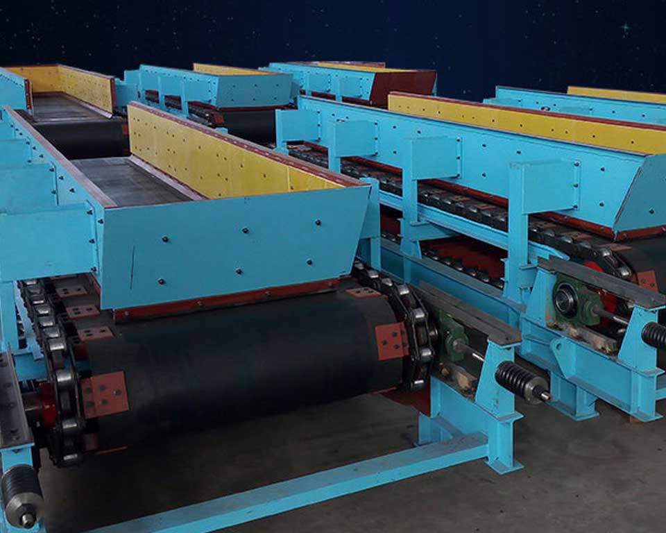
Medium-Duty Plate Apron Feeder
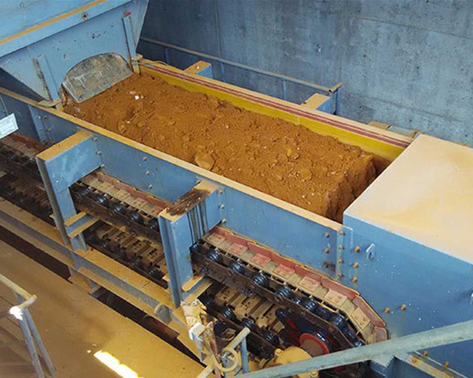
The medium-duty Plate Apron Feeder is suitable for uniform intermittent feeding distributing or transferring various loose materials from the storage bin to the crusher, conveyor, or other working machinery along the horizontal or inclined line. The bulk material whose bulk density does not exceed 2400 kg/m3, the material temperature does not exceed 400 ℃, and the material block weight does not exceed 500kg.
The installation inclination angle of the medium-duty apron feeder is 0-25°, and the transmission device can be installed on the left or right, the right transmission is on the right side of the material running direction, and the left transmission is on the contrary.
Four key points for attention in the installation and use of medium-duty apron feeders
- The center distance of the head and tail wheels of the apron feeder is generally determined by the user according to the space used on the site. The apron feeder is placed under the silo, and the center distance of the head and tail wheels are appropriately increased on the basis of greater than the length of the outlet of the silo. 10 meters is appropriate, too large will increase equipment investment.
- The feeding capacity is determined by the output of the next process that is matched with the apron feeder. For example, the apron feeder feeds the crusher, and the delivery output of the apron feeder is designed to be slightly larger than the output of the crusher.
- The installation inclination is generally determined by the design institute or the user of the apron feeder according to the on-site process layout. For small-distance transportation, the installation angle is generally larger than zero, and for long-distance transportation, the installation angle is between 0-25°.
- Since the apron feeder requires a high-load operation, it is a constant torque device. When the traction force is assumed to be constant, the torque is proportional to the radius of the gyration and has nothing to do with other parameters. The size of the traction force determines the model of the traction chain rail, and the drive sprocket The pitch circle is determined accordingly, then the torque of the main shaft is constant, and the appropriate driving mechanism can be selected according to the above data.
Read More: Apron Feeder: Basics, 3 Types, 4 Features, 5 Diffs, 6 Advantages
Technical Parameters
| Model |
Chute width mm |
Chain wheel center distance mm |
Delivery capacity m3/h |
Chain speed m/s |
The maximum particle size allowedmm |
Motor Power kw |
Weight t |
| B800-3 | 800 | 3000 | 20-320 | 0.03-0.25 | 350 | 2.2-7.5 | 4300 |
| B800-4.5 | 4500 | 5500 | |||||
| B800-6 | 6000 | 6800 | |||||
| B800-9 | 9000 | 3-11 | 9600 | ||||
| B800-12 | 12000 | 12500 | |||||
| B800-15 | 15000 | 16000 | |||||
| B1000-3 | 1000 | 3000 | 30-480 | 0.03-0.25 | 450 | 3-11 | 5500 |
| B1000-4.5 | 4500 | 6800 | |||||
| B1000-6 | 6000 | 8200 | |||||
| B1000-9 | 9000 | 4-15 | 11000 | ||||
| B1000-12 | 12000 | 14000 | |||||
| B1000-15 | 15000 | 5.5-18.5 | 17000 | ||||
| B1000-18 | 18000 | 20000 | |||||
| B1250-3 | 1250 | 3000 | 40-680 | 0.02-0.25 | 580 | 4-15 | 7000 |
| B1250-4.5 | 4500 | 8800 | |||||
| B1250-6 | 6000 | 10500 | |||||
| B1250-9 | 9000 | 5.5-22 | 14000 | ||||
| B1250-12 | 12000 | 18000 | |||||
| B1250-15 | 15000 | 7.5-30 | 22000 | ||||
| B1250-18 | 18000 | 26000 | |||||
| B1600-4.5 | 1600 | 4500 | 45-900 | 0.02-0.2 | 700 | 5.5-22 | 12000 |
| B1600-6 | 6000 | 15000 | |||||
| B1600-9 | 9000 | 7.5-30 | 20000 | ||||
| B1600-12 | 12000 | 26000 | |||||
| B1600-15 | 15000 | 11-37 | 32000 | ||||
| B1600-18 | 18000 | 38000 | |||||
| B1800-4.5 | 1800 | 4500 | 50-1100 | 0.01-0.2 | 800 | 7.5-30 | 16000 |
| B1800-6 | 6000 | 19000 | |||||
| B1800-9 | 9000 | 11-37 | 25000 | ||||
| B1800-12 | 12000 | 32000 | |||||
| B1800-15 | 15000 | 15-45 | 38000 | ||||
| B1800-18 | 18000 | 45000 | |||||
| B2000-4.5 | 2000 | 4500 | 60-1350 | 0.01-0.2 | 900 | 11-37 | 20000 |
| B2000-6 | 6000 | 26000 | |||||
| B2000-9 | 9000 | 15-45 | 32000 | ||||
| B2000-12 | 12000 | 40000 | |||||
| B2000-15 | 15000 | 18.5-55 | 48000 | ||||
| B2000-18 | 18000 | 56000 | |||||
| B2200-4.5 | 45000 | 15-45 | 25000 | ||||
| B2200-6 | 6000 | 32000 | |||||
| B2200-9B | 9000 | 18.5-55 | 39000 | ||||
| B2200-12 | 2200 | 12000 | 48000 | ||||
| B2200-15 | 15000 | 22-75 | 56000 | ||||
| B2200-18 | 18000 | 64000 | |||||
| B2500-4.5 | 2500 | 4500 | 80-1800 | 0.01-0.16 | 1150 | 18.5-55 | 32000 |
| B2500-6 | 6000 | 40000 | |||||
| B2500-9 | 9000 | 22-75 | 48000 | ||||
| B2500-12 | 12000 | 60000 | |||||
| B2500-15 | 15000 | 30-90 | 72000 | ||||
| B2500-18 | 18000 | 84000 |
Note
- The motor power in the table is the value obtained when the installation angle is 0°-15°.
- Choose XW, XWE°XWD, or ZQ type of reducer, and the speed ratio range is 35-1003.
- The total weight is the design weight at the maximum feeding speed when the feeder is installed horizontally and the speed is not adjusted, excluding the weight of the receiving funnel and the guide fence.